A-Com with Arduino Nano
Introduction
Guide to setting up DMComm with Arduino Nano + A-Com circuit.
This document is part of the DMComm Software under the MIT License.
Credit to Ben | Katsu at the Alpha Project for the A-Com circuit.
See also
Circuit
You will need:
- Arduino Nano or clone, with either FTDI or CH340 serial. You can see which serial chip you have by reading the text on the largest chip on the underside of the board (the opposite side from the USB port). Recently a clone has appeared with no text on that chip - this type is not working with the Alpha apps on Android.
- Something to mount the circuit. A mini breadboard with 170 tie points works well.
- Two resistors for the voltage divider. The Alpha guide recommends R1=3.9K, R2=5.6K, and nearly all premade units will use those values. Other similar values are also likely to work. It is better to adjust them closer together rather than further apart (even two equal resistors are quite likely to work unless your USB voltage is on the low side). Be sure to use “K” and not “ohms”!
- Something to connect to the two prongs of the toy. (On 3-prong devices, the 2 outer prongs are joined together.) Two breadboard wires are sufficient, and the ends can be wedged into the toy’s prongs. More elaborate connectors are also possible.
Schematic
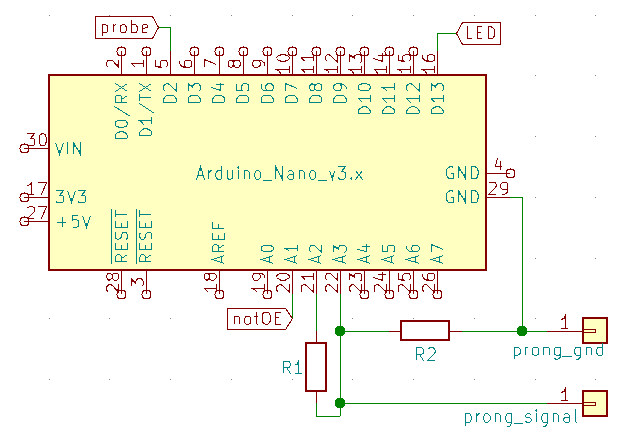
(The pins labelled probe/LED/notOE are used by the program but you don’t need to connect anything to them.)
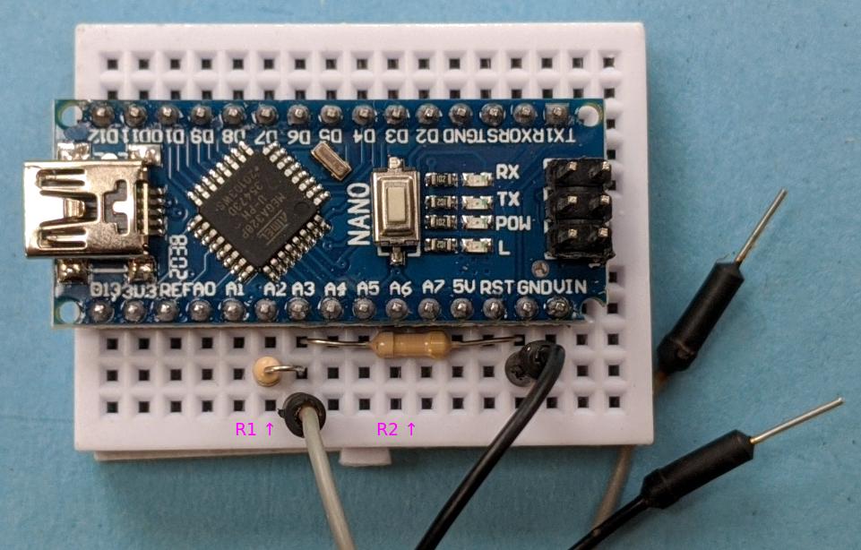
Breadboard example
Arduino IDE
Install the Arduino IDE from the official site. This may also install the required driver.
Driver
Windows
- Open the Device Manager without your Arduino connected.
- Look for “Ports (COM & LPT)”, and “Other devices”, and check if anything is there already.
- Connect your Arduino to the USB and see what appears in the Device Manager.
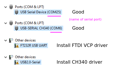
- If it says “COM[number]”, the correct driver is already installed.
- If it says “FT232R USB UART” without a COM number, install the FTDI VCP driver.
- If it says “USB2.0-serial” without a COM number, install the CH340 driver.
Mac
Recent MacOS does not require a driver to be installed. You may need to adjust permissions for the serial port before apps can access it.
If you are running MacOS 10.13 High Sierra or earlier, you may need to install a driver for CH340. Installing CH34x_Install_V1.5.zip from this source has been suggested.
The FTDI link above also has Mac drivers for if your version of MacOS does not include one.
Linux
Linux does not require a driver to be installed. You may need to adjust permissions for the serial port before apps can access it. Typically, there is a group which has access to serial ports, most often named dialout, but could be uucp or something else. Add your user account to the relevant group, then log out and in again.
Flashing
- Download the DMComm sketch and unzip.
- Open the
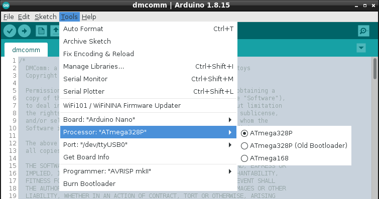
.inofile in the Arduino IDE. - In the “Tools” menu, set the “Board” option to “Arduino Nano”.
- Set the “Port” option to the serial port of your device. On Windows, this will have appeared in the Device Manager as described earlier.
- The correct “Processor” option might be either “ATmega328P” or “ATmega328P (Old Bootloader)”. We just have to guess.
- Click the “Upload” button and wait. If it was unsuccessful, select the other “Processor” option and try again.
Voltage test
After the upload was successful, open the Serial Monitor. Make sure the drop-down menus are set to “Newline” and “9600 baud”. Send the letter “t” by itself and review the results. The measured voltages should be similar to the following. If they are not, there is a mistake or a bad connection in your circuit!
got 1 bytes: t -> [test voltages]
Reference declared: ~5V
Enabled high (40ms): 576 units = 2.7-3.0V
Enabled low (40ms): 0 units = 0.0-0.0V
Disabled low (40ms): 0 units = 0.0-0.0V
Disabled high (100ms): 576 units = 2.7-3.0V
A-Com detected
Connection
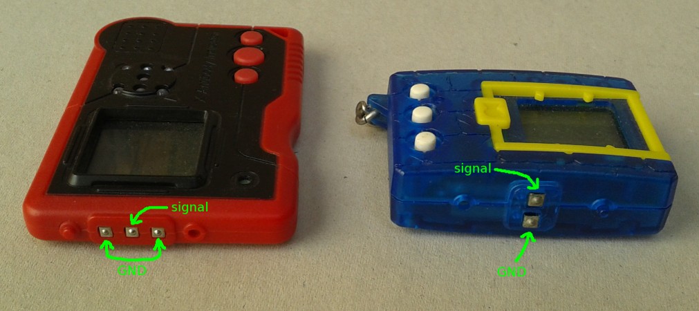
The GND prong on the toy connects to GND in the circuit, and the signal prong on the toy to the A3 pin on the Arduino. For 3-prong devices, only one GND prong needs to be connected.
Choose an appropriate DigiROM for the toy you have, paste it into the Serial Monitor and send it. Select the corresponding option in the toy’s menus, and attempt to connect. If the second character of the DigiROM was “2”, you will need to press a button on the toy to initiate the communication, then keep the devices connected for a few seconds after pressing it. If that character was “1” (as in the examples below), leave the buttons alone and wait with the devices connected for at least 10 seconds. If the communication fails, please copy the results from the Serial Monitor when asking for help.
DigiROM examples:
V1-FC03-FD02- original battle - also works with the original Pendulum, and with the “other” battle mode on modern devices.V1-9841-2201-8001-3A01-2001- Pendulum Progress battle.X1-0159-4379-0009-C009- Pendulum X battle - also works with Mini, Accel and iC.Y1-1017-0097-2E47-@C1F7- Xros Mini battle.
More can be found on Humulos’s site.